Tatsumi Kimishima, Nintendo’s president, claimed in a Time interview that Nintendo are not developing the new version of Wii or Wii U with NX. This new system will be unique and different.
Those words could fit with the following patent registered by the Big N.
Abstract
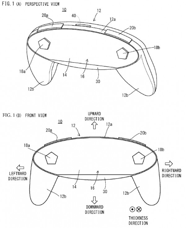
A non-limiting example information processing apparatus comprises a housing, and a first portion of the housing is formed in an elliptical form when viewing from the front. A display panel and a touch panel constitute one main surface of the first portion. Holes are formed in left and right end portions of the display panel and the touch panel, and two operation sticks are provided through the two holes. When viewing the first portion from the front, an area except key tops of the operation sticks becomes a display area.
Fig. 1
With reference to FIG. 1, a non-limiting example information processing apparatus 10 includes a housing 12, and a display panel 14 constitutes one main surface (front surface) of the housing 12. As the display panel 14, an LCD, EL, etc. can be used, for example. Furthermore, as the display panel 14, it is possible to use a display panel allowing stereoscopic view with naked eyes. In such a case, an LCD of a parallax barrier system or an LCD of a lenticular system using a sheet with unevenness (lenticular lens) is used, for example.
Furthermore, since the display panel 14 is made into an oblong form as mentioned above, it is possible to make an aspect ratio thereof comparable to a ratio (16:9) of a wide screen.
Although not shown in FIG. 1(A) and FIG. 1(B), a touch panel 16 is provided on the front surface of the display panel 14, and the touch panel 16 is set the same form (size) as the display panel 14 in this embodiment. That is, the touch panel 16 is also an oblong form, and an elliptical form that a part of a long side of a lower end is made into a form of a straight line. Therefore, it is possible to perform a touch input in almost a whole of a display area of the display panel 14. However, the touch panel 16 may be an elliptical form as similar to the form of the front surface of the first portion 12a. Furthermore, as the touch panel 16, a touch panel of an electrostatic capacitance system or a resistance film system can be used.
Furthermore, the information processing apparatus 10 comprises a first operation stick 18a, a second operation stick 18b, a first operation button 20a and a second operation button 20b. The first operation stick 18a is provided in a position operable by the thumb of the left hand when the player holds the information processing apparatus 10 with one hand or both hands, and similarly, the second operation stick 18b is provided in a position operable by the thumb of the right hand. Furthermore, the first operation button 20a is provided in a position operable by the index finger of the left hand when the player holds the information processing apparatus 10 with both hands, and similarly, the second operation button 20b is provided in a position operable by the index finger of the right hand. In this embodiment, the first operation button 20a and the second operation button 20b are provided on a side surface of the first portion 12a. More specifically, the first operation button 20a is provided in a left end portion of an upper surface of the housing 12, and the second operation button 20b is provided in a right end portion of the upper surface of the housing 12.
Furthermore, a card slot 40 is provided in a center portion of the upper surface of the housing 12. The card slot 40 can be attached with various kinds of card storage media such as a game cartridge, an SD card, a SIM (Subscriber Identity Module) card, etc. Therefore, the information processing apparatus 10 reads (acquires) a program and data from the card storage medium that is attached to the card slot 40, or writes a program and data into a card storage medium. It should be noted that the program is a program for an application such as a game, and the data is data used for processing of the application. Furthermore, in some cases, a personal authentication may be performed.
In addition, although omitted in FIG. 1(A) and FIG. 1(B), the information processing apparatus 10 comprises a speaker 64 (see FIG. 19), and the speaker 64 is provided inside the housing 12, for example. However, a hole for outputting a sound from the speaker 64 to outside the housing 12 is provided in a portion other than the display area of the display panel 14, i.e., a side surface or the rear surface of the housing 12.
Fig. 9
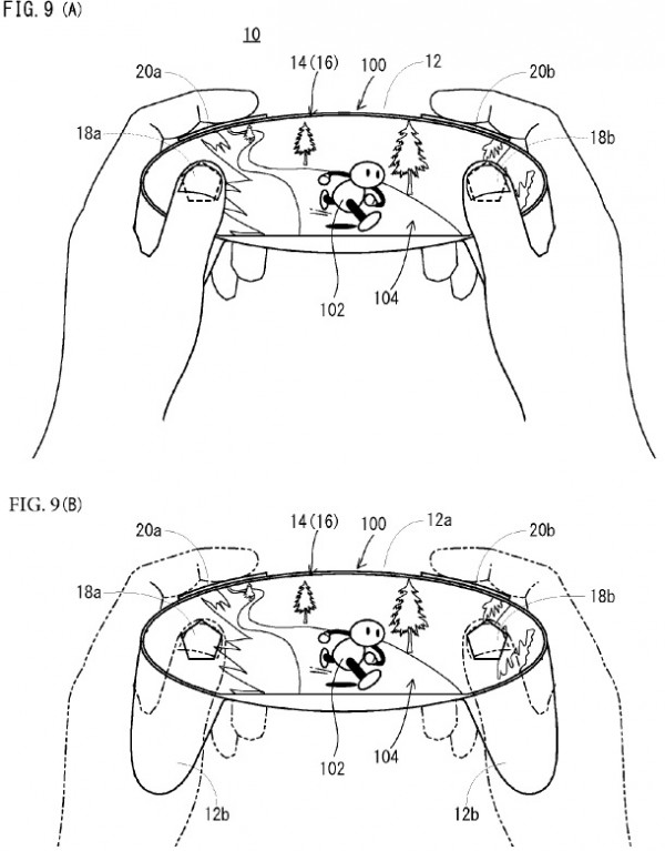
FIG. 9(A) and FIG. 9(B) show an example of a case where a virtual game space (game screen 100) is displayed on the display panel 14 of the information processing apparatus 10 and the player plays a game. The game screen 100 is an image that the virtual game space in which a predetermined object is provided is imaged by a virtual camera. Specifically, a predetermined character or predetermined object such as a background, a person etc. is provided (rendered) in a three-dimensional space such as the virtual game space, and a two-dimensional image that is viewed from the virtual camera (viewpoint) is generated. That is, an image of the three-dimensional space viewed from the viewpoint is projected on a two-dimensional virtual screen by viewpoint conversion processing such as perspective projection transformation, and a projected two-dimensional image is displayed as the game screen 100.
Fig. 10
FIG. 10 shows a further example of the game screen 100. In the game screen 100 shown in FIG. 10, a button image 110 is displayed near the second operation stick 18b. If the button image 110 is touched, for example, according to this, an instruction that is set to the button image 110 is input. Therefore, by assigning to the button image 110 an instruction different from an instruction that is input when depressing the second operation stick 18b, it is possible to input more variegated instructions. Furthermore, if the button image 110 is displayed supplementally (or additionally or supportively) to the second operation stick 18b in a range near the second operation stick 18b and the thumb on the right hand of the player reaches, it is possible to use the second operation stick 18b and the button image 110 as such a push button of the common game controller.
In addition, a position that displays the button image 110 may be set arbitrarily by the player. For example, if the button image 110 is displayed in a range near the first operation stick 18a and the left thumb reaches, it is also possible to make it button arrangement that is easy to operate for the player of a left-handed player who operates a push button with the left thumb. Furthermore, the button image 110 may be displayed outside the first operation stick 18a or the second operation stick 18b, whereby the center part of the game screen 100 can be made conspicuous.
Furthermore, the button image 110 should just be displayed at a proper timing such as a case of being required for operation of a game, and does not need to be displayed always.
Fig. 11
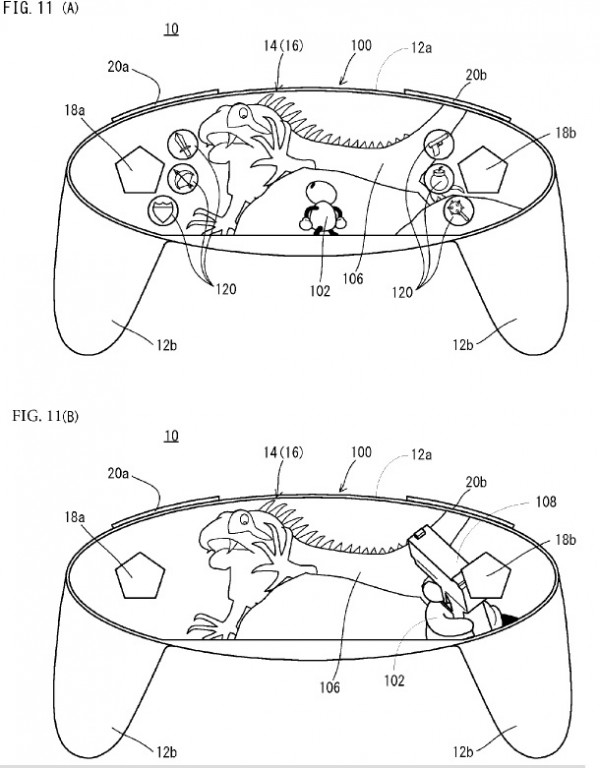
FIG. 11(A) and FIG. 11(B) show a further example of the game screen 100. An enemy character 106 is displayed in a screen center of the game screen 100 shown in FIG. 11(A), and the player character 102 turns to the enemy character 106. Furthermore, near each of the first operation stick 18a and the second operation stick 18b, a plurality of item images 120 are displayed. Although illustration is omitted, a background image is also displayed in the game screen 100 shown in FIG. 11(A) (FIG. 11(B) is the same).
On the game screen 100 shown in FIG. 11(A), by touching the item image 120, an item can be used. Since the item image 120 is thus displayed near the first operation stick 18a and the second operation stick 18b, it is possible to use an item by selecting a desired item by a touch input and depressing the first operation stick 18a or the second operation stick 18b near the item, for example. This is an example and should not be limited. When instructing the use of an item, the first operation stick 18a or the second operation stick 18b should just be pushed.
In addition, the item image 120 is displayed about the item that the player character 102 owns. Furthermore, the item image 120 should just be displayed according to a predetermined timing (event) such as a case where there is a displaying instruction by the player or a case of battling against the enemy character 106, and does not need to be displayed always.
In the game screen 100 shown in FIG. 11(A), for example, if the item image 120 that an image of a gun is drawn is selected (touched), it is determined that the player character 102 uses a gun object 108. Then, the game screen 100 as shown in FIG. 11(B) becomes to be displayed on the display panel 14. The game screen 100 shown in FIG. 11(B) is drawn with a first-person viewpoint of the player character 102, and a part of hand of the player character 102 is displayed. Furthermore, since having determined the use of the gun object 108 as mentioned above, the gun object 108 is grasped by the hand of the player character 102. A point that the enemy character 106 is displayed in the screen center is the same as the game screen 100 of FIG. 11(A). Furthermore, since the item to be used is selected, the item image 120 is non-displayed in the game screen 100 shown in FIG. 11(B).
As shown also in FIG. 11(B), the part of the hand of the player character 102 and the gun object 108 are displayed near the second operation stick 18b. For example, an operation that makes the gun object 108 move or shoot a bullet is performed by the second operation stick 18b. Therefore, since the gun object 108 is displayed near the thumb of the player, a feeling that the player is directly operating the gun object 108 is obtained.
That is, since the game screen 100 drawn from the first-person viewpoint is displayed on the display panel 14 having a form similar to a form of the visual filed of the human being, the player can obtain a feeling of immersion into the virtual game space. Furthermore, since the gun object 108 is displayed near the thumb of the player, it is thought that a higher feeling of immersion can be obtained.
Fig. 12 & 13
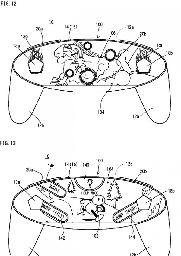
FIG. 12 shows a further example of the game screen 100. In the game screen 100 shown in FIG. 12, an enemy character 106 is displayed in the screen center and a background image 104 in a manner that a spark is scattered in part and is full of smoke is displayed. Furthermore, an object (flame object) 130 that imitates flames is displayed around the first operation stick 18a and the second operation stick 18b. For example, it is shown a situation that by operating at least one of the first operation stick 18a and the second operation stick 18b by the player, the player character is caused to emit the flame to attack the enemy character 106 with the spark and smoke generated by the flame. Thus, by displaying an image effect corresponding to a physical operation of the player around the operation stick (18a, 18b), it is possible to display the game screen 100 with ambience. Therefore, it is possible to more raise a feeling of immersion.
FIG. 13 shows a further example of the game screen 100. In the game screen 100 shown in FIG. 13, a player character 102 and a background image 104 are displayed as shown in FIG. 9(A) and FIG. 9(B). Furthermore, in the game screen 100 shown in FIG. 13, an index image 140 indicative of a help mode is displayed in an upper end portion in the screen center and a character string of “help mode” is displayed below the same. Furthermore, a guide image 142 is displayed near the first operation stick 18a. Here, the guide image 142 is displayed in the game screen 100 in contact with the first operation stick 18a or its key top in appearance. Similarly, a guide image 144 is displayed near the second operation stick 18b. Similarly, a moving image 146 is displayed near the first operation button 20a. The guide images 142, 144 and 146 are images for explaining an operation content (the content of instructions) of corresponding touch panel 16, operation stick (18a, 18b) and operation button (20a, 20b). In addition, the guide images 142 and 144 explain not only the operation content but an operation method. Therefore, it can be understood that if tilting the first operation stick 18a in a direction that the guide image 142 is extended, it is possible to move the player character 102 in the virtual space in the direction that the guide image 142 is extended in the screen, for example. It can be understood that if depressing the second operation stick 18b, it is possible to make the player character 102 jump. Then, it can be understood that if pushing the first operation button 20a, it is possible to make the player character 102 squat.
Fig. 14 & 15
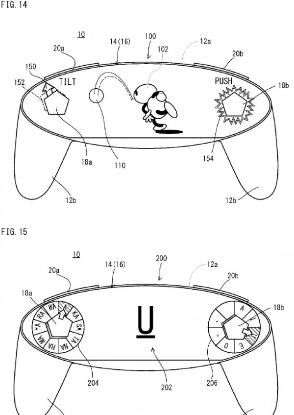
FIG. 14 shows a further example of the game screen 100. In the game screen 100 shown in FIG. 14, a player character 102 in a manner of throwing an object (ball object) 110 that imitates a ball is displayed. Furthermore, near the first operation stick 18a, an arrow mark (guide image) 150 that points a predetermined direction (here, left slant upper) is displayed, and a guide image 152 that is for indicating that the first operation stick 18a is tilted in a direction that the arrow mark points and imitates the key top portion 1800 of the first operation stick 18a is displayed while being blinked, for example. In FIG. 14, a dotted line shows that the guide image 152 is blinking. However, it is not necessary to make blink. Furthermore, near the guide image 150, a character string of “tilt” is displayed. Furthermore, the guide image 154 that shows that the second operation stick 18b is to be pushed is displayed around the second operation stick 18b, and a character string of “push” is displayed near this guide image 154.
FIG. 15 shows an example of a character input screen 200. A display area 202 that displays an input character in the screen center is formed in the character input screen 200 shown in FIG. 15. Guide images 204 for inputting a consonant (Japanese “a”-“wa” columns) are displayed around the first operation stick 18a. Furthermore, guide images 206 for inputting a vowel (rows of syllables on the Japanese syllabary table that ends with the vowel sound “a”-“o”) and punctuation are displayed around the second operation stick 18b.
Fig. 19
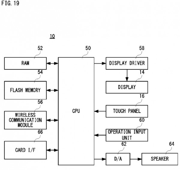
FIG. 19 is a block diagram showing non-limiting example electric structure of the information processing apparatus.
Thanks, NeoGAF.



![[Rumor] Marvel’s Spider-Man, The Golf Club 2019 and Just Cause 4 new games to join PS Now](https://vgleaks.com/wp-content/uploads/2020/04/spidey.jpg)
![[Leak] Elden Ring two new artworks and details emerged](https://vgleaks.com/wp-content/uploads/2020/12/elden-ring.jpeg)


![[Rumor] GTA 6 to be digital-only at launch… to avoid story spoilers](https://vgleaks.com/wp-content/uploads/2024/03/gta-6-150x150.jpg)
![[Rumor] Resident Evil: Code Veronica remake could be announced this year and launch in 2027](https://vgleaks.com/wp-content/uploads/2026/01/resident-evil-code-veronica-150x150.jpg)
